XR-100CR Si-PIN Application Spectra
The most common applications of the XR-100CR are in the field of X-Ray fluorescence, or XRF. This is an analytical technique which determines the elements present in a sample, and does so non-destructively and very rapidly.
RoHS/WEEE Application
Alloy Analysis: XRF of SS316, XRF of Ag/Cu
XRF of lead (Pb)
Metal Plating
Process Control
XRF of a Saint Gaudens US $20 Gold Coin
XRF of a Various Jewelry
Glass Analysis
Paper Analysis
Mössbauer Spectroscopy
Multi-Element Fluorescence Sample
Low Z Element Fluorescence
241Am Spectrum
RoHS/WEEE Application
The RoHS / WEEE [Restriction of Hazardous Substances / Waste from Electrical and Electronic Equipment] directive requires that the electronics industry certify that products comply with maximum concentration amounts of particular elements and compounds (Cr VI, Pb, Cd, Hg, Br PBB/PBDE) by July, 2006. The chart below shows the X-ray spectrum emitted by a combination of chromium (Cr), lead (Pb), and cadmium (Cd). The XR-100CR can be used to verify compliance with the RoHS/WEEE requirements as part of a quality assurance program, via XRF. It permits users to measure the concentration of the specified elements, quickly, accurately, and non-destructively. Companies can verify supplier compliance and demonstrate their own compliance.

Figure 8. Chromium (Cr), lead (Pb), and cadmium (Cd) XRF. The RoHS / WEEE directive requires that the electronics industry certify product to comply with maximum concentration amounts of particular elements and compounds (Cr VI, Pb, Cd, Hg, Br PBB/PBDE) by July, 2006.
XRF of SS316
XRF can be used to determine exactly the alloy of a particular piece of metal. Each alloy has a unique ratio of elements, and with XRF, one can non-destructively determine the ratio of elements from the ratio of the intensities of the peaks. The spectrum below shows the spectrum of X-rays emitted from a piece of stainless steel 316, when excited by 109Cd. The strong Fe line indicates that this is based on iron, while the Cr, Mn, Ni, and Mo peaks can be used to identify the alloy. This can be very important in numerous applications, such as quality assurance (verifying a vendor used the correct alloy), process control, metal recycling, etc.

Figure 9. X-Ray Fluorescence (XRF) of SS316 from 109Cd.
XRF of Silver (Ag) and Copper (Cu) Alloy
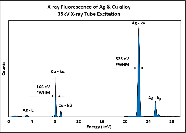
Figure 10. XRF of Silver (Ag) and Copper (Cu) Alloy.
XRF of lead (Pb)
A very important special case in the field of metals analysis is that of lead (Pb). Lead has been commonly used in many products for years, from paint to plumbing solders to electronic assemblies. XRF provides a non-destructive method to assess whether or not lead is present in an item, without damaging the item. The spectrum below shows the characteristic L X-rays emitted from a piece of pure lead, with a 109Cd excitation source.

Figure 11. X-Ray Fluorescence (XRF) of lead (Pb) from 109Cd.

Figure 12. Lead (Pb) Fluorescence showing both K and L lines.
Plating on a Steel Connector
The spectrum below show the plating on electronic connectors. Since Cd cannot be used in certain connector applications, it can be important to verify its presence or absence. This spectrum clearly demonstrate that Cd and Cr were both used in the plating on the steel connector.

Figure 13. Cadmium & chromium plated steel
Gold (Au) Plated on Nickel (Ni)

Figure 14. Gold plated on nickel
XRF of Galvanized Steel

Figure 15. Galvanized Steel: Zinc (Zn) plating on Iron (Fe).
Process Control: XRF of Smoke Stack in Steel Plant

Figure 16.
XRF of a Saint Gaudens US $20 Gold Coin
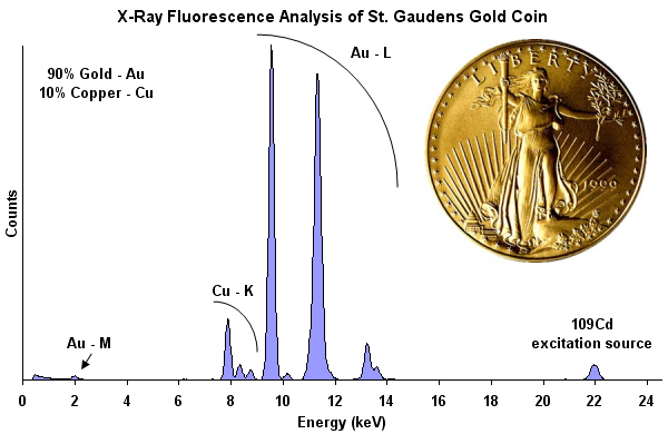
Figure 17. XRF analysis of a Saint Gaudens US $20 gold coin with 90% Gold (Au) and 10% Copper (Cu).
XRF of a Platinum (Pt) Ring
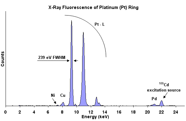
Figure 18. Analysis of a Platinum (Pt) ring containing Copper (Cu), traces of Nickel (Ni), and Palladium (Pd).
XRF of a 14k Gold/White Gold (Au) Chain
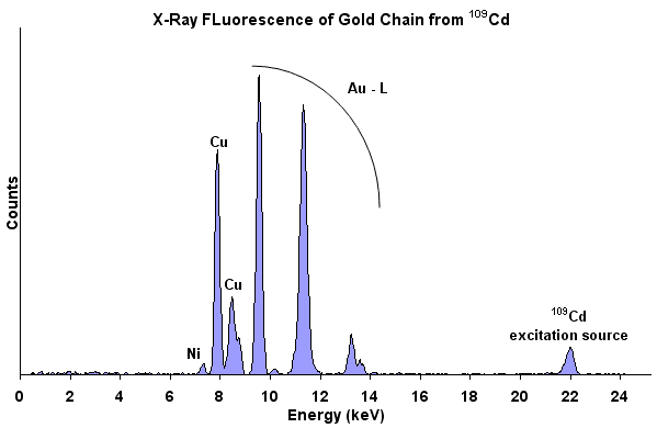
Figure 19. Analysis of a 14k Gold/White Gold (Au) chain containing Copper (Cu) and Nickel (Ni).
XRF of Glass
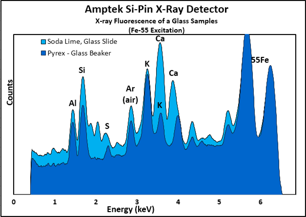
Figure 21.
XRF of Paper

Figure 22.
Mössbauer Spectroscopy
The XR-100CR 7 mm2/300 µm detector is an excellent detector for Mössbauer Spectroscopy. Since the thickness of the detector is only 300 µm, it is very efficient at 14.4 keV and very inefficient at 122 keV. The 57Co spectrum shown here shows a detection efficiency ratio between 14.4 keV and 122 keV of about 1700/1. By using a thin Aluminum absorber between the detector and the source, the 6.4 keV and 7.1 keV peaks can also be eliminated, leaving the 14.4 keV as the only detectable energy peak.

Figure 24.
Multi-Element Fluorescence Sample

Figure 25. X-ray fluorescence (XRF) of multi-element sample from109Cd.
Low Z Element Fluorescence
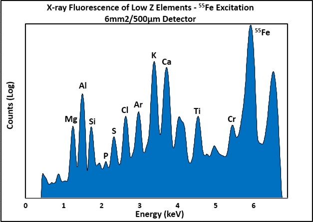

Figure 26. Low (Z) element x-ray fluorescence (XRF) with 6 mm2/500 µm detector.
241Am Spectrum

Figure 27. 241Am Spectrum.